12 June 2018

UK DEFENCE MINISTER VISITS WFEL

World leader in rapidly-deployable military bridges hosts UK Defence Minister

As one of Britain’s leading military equipment suppliers, WFEL was delighted to host Defence Minister Guto Bebb during a visit to our Stockport manufacturing facility yesterday.

The Minister was keen to discover more about WFEL’s technical capabilities within the defence sector and took the opportunity to tour the defence manufacturing facilities and meet with the engineering teams.

Guto Bebb saw first-hand the latest developments across a full range of rapidly deployable bridging systems, including many products destined for export to overseas military customers.

During the tour, the Minister and his team were given a demonstration of the complete build and launch of a DSB Dry Support Bridge, which can be deployed in under 90 minutes by a team of only 8 personnel and can support an MLC of 120 whilst spanning a 46 metre gap. This bridge is currently being evaluated by the UK MoD as part of their Tyro Bridging Capability Project.

Defence Minister Guto Bebb said, “WFEL provides world-class bridge systems that enable UK Armed Forces to be rapidly deployed across the globe and project military power in any eventuality.

“Defence suppliers are at the heart of British industry and the MOD will ensure that our home-grown companies continue to develop, thrive and export their innovative products to our international partners.”

WFEL’s Managing Director, Ian Anderton, also took the opportunity to demonstrate to the Minister the broad spectrum of WFEL’s engineering expertise, including recent technology transfer projects for both UK and overseas customers, which includes the Leguan Close Support Bridge, as well as highlighting recent capital investment in the latest state-of-the-art equipment. Ian Anderton said, “Having been a proud supplier to the UK MoD for over thirty years, we are delighted to welcome Minister Bebb to our facilities. This has allowed us to further showcase our defence manufacturing facilities, including the latest technological investments and we are pleased that the Minister was keen to meet with our employees across the various departments. We look forward to continuing our relationship with the UK MoD for many years to come.”

6 June 2018

WFEL HOSTS AUSTRALIAN DOD CASG

WFEL hosts Australian Department of Defence Capability Acquisition and Sustainment Group

WFEL had the privilege of welcoming this week Brigadier Ed Smeaton - Director General Land Manoeuvre Systems of the Australian Department of Defence - to its defence manufacturing facilities.

Brigadier Smeaton’s organisation, which is part of the Capability Acquisition and Sustainment Group, is responsible for the acquisition and through-life support of a wide range of land-based capabilities required by the Australian Defence Force (ADF), including bridging.

Brigadier Smeaton was delighted to be shown around WFEL’s production facility, which is currently supplying a number of its Dry Support Bridges (DSB) and Medium Girder Bridges (MGB) to the ADF under the Land 155 Phase 1 Enhanced Gap Crossing Capability project.

The Brigadier was also keen to discover more about WFEL’s wider technical capabilities within the defence sector, and to see the latest developments across a full range of rapidly deployable bridging products.

As a long-standing user of WFEL’s MGB bridges since the 1970’s, the ADF has recently taken delivery of their first new sets of WFEL’s rapidly deployable bridging systems, and the Brigadier was keen to observe the technical operations behind the manufacture of these bridges.

After having been shown around the facilities by WFEL’s Managing Director, Ian Anderton, Brigadier Smeaton commented, “My visit today was extremely informative and your team were both passionate and engaging. It was a particularly good opportunity to understand the design and complexity that goes into the manufacturing of your bridging products. As a customer and user, it was reassuring to see the level of testing and quality assurance completed at each stage in the process.”

Ian Anderton added, ‘We are extremely proud to have supplied our Australian customer with a world-leading set of bridging systems and we look forward to developing further our ongoing relationship”.
WFEL will be attending the Eurosatory show next week in Paris.

14 April 2018

WFEL APPOINTS FORMER BAE SYSTEMS MANAGING DIRECTOR

WFEL Ltd is pleased to announce the appointment of Ian Anderton as Managing Director, succeeding Ian Wilson, who will shortly retire from the company.

Ian Anderton brings with him extensive experience of the defence industry, coupled with a strong background in operational improvement.  For many years, Ian held senior management roles within BAE Systems, including Managing Director of the Munitions Division and COO roles within BAE’s Maritime Division, responsible for both submarines and warships.

Prior to his time at BAE, Ian was General Manager for Pirelli Power Cables and also spent some 12 years in a variety of leadership roles within ICI.

Ian said, “WFEL’s military bridging products have a worldwide reputation for quality and adaptability and I am delighted to be joining the organisation, which I see as a company with a tremendous heritage and with great potential for future growth.  I am very much looking forward to helping the business further develop.

“I have already been impressed with the dedication, passion and depth of technical ability within the WFEL team and, together, we will focus on addressing the developing needs of our increasing worldwide customer base, to ensure we remain a world-leading supplier of military bridging equipment.” In order to ensure a smooth transition, Ian Wilson will remain with the company until the summer. Commenting on his forthcoming retirement, Ian Wilson said, “After more than 30 years at WFEL, it is now time to hand over the reins and I am supremely confident of leaving the company in the very capable hands of Ian Anderton, who will play a vital role in driving the company forward through its next period of growth."

6 March 2018

WFEL COMPLETES AUSTRALIAN LAND 155 FIRST TRANCHE BRIDGING DELIVERY

Under the Land 155 Enhanced Gap Crossing Capability Project, the Australian Defence Force (ADF) has taken delivery of the first scheduled tranche of WFEL’s rapidly deployable military bridges, including Dry Support Bridges and Medium Girder Bridges. This project milestone includes some of the first configurations of the Dry Support Bridge launching vehicle on a fully-armoured Rheinmetall MAN Military Vehicle (RMMV) 45m 10 x 10 chassis.

The Dry Support Bridges (DSBs), capable of carrying over 120 tonnes, have been delivered following extensive trials at the UK’s Millbrook Proving Ground, to verify both off-road and on-road capability and in accordance with a series of demanding mandated Specifications, Audits and Project Reviews determined by the Australian Government. Also supplied for Land 155 are WFEL’s double-storey, link-reinforced Medium Girder Bridge systems (MGBs), which can span up to 49 metres and which will be supplemented by additional portable Pier and Span equipment, allowing bridges of up to 76 metres to be constructed.

As the bridges provide temporary infrastructure and will be used in the ADF’s Combat Support and Disaster Relief operations, both DSB and MGB bridging systems are being delivered complete with walkways, to allow the separation of vehicular traffic from pedestrians. WFEL’s comprehensive Integrated Logistics Support package is also being supplied, to cover through-life support for the bridges.

The adoption and acceptance of the latest variant of the DSB by Australia further helps to support WFEL’s position in respect of ‘Project Tyro’, the Assessment Phase program contract that it won to look at replacing the UK’s ageing BR90 systems nearing their end of service.


The DSB - which can be launched by just 8 personnel within 90 minutes, is already in use with the US, Swiss and Turkish armed forces and has been proven in the field as temporary infrastructure in Iraq and Afghanistan - fulfils the demanding requirements for the Tyro Project through a proven and validated track record, providing an off-the-shelf, low risk solution to the UK MoD’s wide-gap tactical bridging requirements. The UK MoD, just like the Australian Defence Force, is already familiar with WFEL’s bridging systems, having been a user of the modular Medium Girder Bridges since the 1970s.


WFEL is also currently fulfilling further DSB orders for the U.S. Army - an experienced user of the DSB since 2003 - in support of its European Deterrence Initiative. This supply of additional Dry Support Bridges will bring the U.S. Army’s stockholding up to almost 120 systems.


Ian Wilson, Chief Executive of WFEL, commented, “WFEL’s long-standing relationship with the Australian Defence Force began over 30 years ago, when they chose our Medium Girder Bridges. We are delighted to continue to support them today, this time not only with further MGBs, but with a significant capability enhancement through the purchase of the latest mechanised DSB. The adoption of the DSB not only provides the ADF’s Manoeuvre Commanders with the ability to cross significant wet or dry gaps quickly and efficiently, it allows a level of inter-operability with an ever-growing user base.


“This significant and growing installed base of DSB equipment, allied to our fully-operational production line, ensures that WFEL’s customers have a high level of confidence not only in our products but also in our continued through-life support and spares availability.”


WFEL will complete final delivery of the ADF’s bridges by September 2018.

12 October 2017

JANE’S FEATURES WFEL’S F35B SKI JUMP’S INVOLVEMENT IN HMS QUEEN ELIZABETH TRIALS

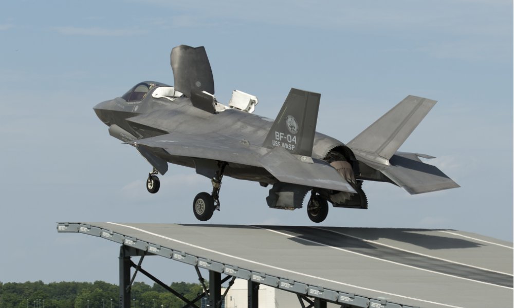
THE F-35 INTEGRATED TEST FORCE AT NAS PATUXENT RIVER IS ONCE AGAIN CONDUCTING LAND-BASED SKI-RAMP TESTING IN PREPARATION FOR TRIALS ON HMS QUEEN ELIZABETH PLANNED FOR 2018, USING THE TAKE-OFF RAMP WHICH WFEL DESIGNED, DEVELOPED AND MANUFACTURED.

The following special report by Richard Scott was recently featured in Jane’s International Defence Review and is published here with kind permission from IHS Jane’s.

The idea of using a ramp to improve short take-off (STO) performance from a carrier flight deck is generally credited to a thesis completed by Lieutenant Commander Doug Taylor RN in 1973. His research project at the University of Southampton, which was exploring options to improve the operation of fixed-wing vertical/short take-off and landing aircraft from confined spaces, theorised the benefits of introducing a curved ramp or ‘ski-jump’ at the forward end of the flight deck.

Lt Cdr Taylor’s calculations identified that the effect of the ramp was to allow an aircraft such as the Harrier — powered by a vectored thrust engine using swivelling nozzles — to launch upwards on a semi-ballistic trajectory at a speed somewhat less than that required for a ‘flat deck’ STO. This translated to a shorter deck run, higher launch weight, or both.

Work on the ramp concept was further advanced by Hawker Siddeley Aviation’s Kingston division in co-operation with the Ministry of Defence (MoD) through computer modelling and simulation work. These studies confirmed the predicted performance gains and led to the actual flight testing in 1977 using an adjustable ramp constructed at the Royal Aircraft Establishment’s test facility at Bedford.

The trials, which were performed at exit settings ranging from 6.5° through to 20°, provided conclusive evidence of the benefits afforded to Harrier performance. The Royal Navy’s new carrier (CVS) HMS Invincible, by then nearing completion, was modified in build to receive a 7° ski-jump, as was second-of-class HMS Illustrious. A 12° ramp was fitted to HMS Hermes at refit, and the design of HMS Ark Royal modified to accommodate a similarly angled ramp; Invincible and Illustrious later received 12° ramps during refit.

On 30 October 1980, a Sea Harrier FRS.1 became the first fixed-wing short take-off vertical landing (STOVL) aircraft to launch from Invincible. This marked the first aircraft launch from a ski-jump at sea.

Forty years on from those first flight tests at Bedford, land-based testing is currently underway at Naval Air Station (NAS) Patuxent River, Maryland, to refine the ski-jump manoeuvre for the Royal Navy’s new Queen Elizabeth class (QEC) aircraft carriers. This activity, using the F-35B variant of the Lightning II strike fighter, is building evidence ahead of fixed-wing First of Class Flight Trials (FOCFT) on HMS Queen Elizabeth scheduled for late 2018.

The ski-jump ramp works by imparting an upward vertical velocity and ballistic profile to the aircraft, providing additional time to accelerate to flying speed while ensuring it is on a safe trajectory. This additional time is manifested either in a reduced take-off length for a given weight, or increased launch weight (fuel and/or ordnance) for a fixed take-off distance.

This additional performance does not come for free, however, with a significant increase in landing gear loads above those of a standard take-off (albeit low compared with a landing). The increase represents the energy transferred to the aircraft as it translates up the ramp; and if the angle and curvature of the ramp are increased to obtain greater performance benefit, so are the loads.

Although the basic physics of a Ski Jump STO remained unchanged, the F-35B pilot has the big advantage of being able to rely on technology rather than technique, according to Pete ‘Wizzer’ Wilson, BAE Systems F-35 STOVL lead test pilot. “The single key difference between a ski-jump in the Harrier [and] the F-35B is the pilot action right at the end of the ski-jump, just as the aircraft is becoming airborne,” he told Jane’s. “In the Harrier, the pilot had to manually move the nozzles “downwards” at the correct time. In the [F-35B], the control law does it automatically.

“While this may sound like a relatively small change, it’s actually very significant. One of the often talked about problems with the Harrier was the fact that it had three levers for the pilot to control with two hands: the stick, the throttle, and the nozzle lever. While the pilot’s right hand was enough to control aircraft attitude with the stick, it was quite common for the pilot to make a mistake with the left hand, which was required to operate both the throttle and the nozzle lever. This led to many accidents, scattered through the history of Harrier operations.”

The F-35B is very different, with a throttle on the left and a stick on the right. Software — embodied in the aircraft’s advanced control law — takes care of the rest. “Push the throttle to full power, release the brakes, and steer towards the centre of the ski-jump. That, in a nutshell, is what the F-35B pilot has to do during a ski-jump launch,” said Wilson.

“The Ski Jump STO mode requires no action on the part of the pilot other than to ensure the aircraft is steered up the ski-jump. This is a crucial piece of the design since it means the pilot can’t make the mistake of selecting the ‘wrong’ type of take-off, for example selecting a Ski Jump STO when it is actually a Flat Deck STO.”

It is a far cry from the busy cockpit of the Harrier, where the pilot needed to set the correct trim setting before releasing the brakes, move the left hand from the throttle to the nozzle lever after pushing the throttle to full power, and then adjust the nozzles downward at just the right time. The Harrier’s flyaway characteristics were also less predictable. “It was not uncommon to have to control angle of attack once airborne,” Wilson said. “The automatics of the F-35B make the ski-jump launch extremely straightforward for the pilot; in contrast, the Harrier was much higher workload and comparatively much higher risk.”

QinetiQ flight test engineer Gordon Stewart, who has spent much of the last five years attached to the joint US/UK F-35 Integrated Test Force at Patuxent River, points out that making STOVL easy was an important design consideration for the F-35B control law. “Because of the high level of automation embodied, a ski-jump launch is in fact the most straightforward take-off manoeuvre for the STOVL variant of the Lightning II,” he explained to a Royal Aeronautical Society audience in May this year. “When the pilot slams the throttle, the control law is configuring the aircraft for maximum acceleration.”

At the point the aircraft accelerates up the ramp, the control law detects the change in pitch rate and attitude. “That’s the point where it transitions into ski-jump mode,” Stewart said. “Once that occurs, the aircraft has approximately one second to transition to flyaway.”

During that brief period, the control law is configuring the aircraft to minimise the pitch transient on exiting the ramp. It achieves this by setting the horizontal tail position, repositioning the angle of the engine nozzle, and changing the balance/rate of thrust between the lift fan and the aft nozzle. “The thrust split moves forward on the ramp, then back after exit,” said Stewart. “That rapid change in ratio to balance [the aircraft in airborne flight] reflects what’s happening coming off the ramp.

The aircraft is controlling the pitch attitude off the ramp [and is] effectively ‘open loop’ for a very short period of time afterwards.” As part of the F-35 System Design and Development phase, a land-based ski-ramp — modelled on the legacy design used in the RN’s earlier Invincible-class CVS — has been built at Patuxent River to support UK testing. Initial testing was focused on assessing the F-35B’s flying qualities, performance, and undercarriage response during a ramp-assisted take-off.

Test plan development for these Phase 1 Ski Jump STO trials began in earnest back in 2014 using offline and manual simulation. “We started control room training [for the flight test team] and mission rehearsals at the end of the year,” Stewart said. “We performed literally tens of thousands of offline runs in the simulator. That allowed us to look at variations across a whole range of parameters, and also allowed us to develop our launch planning tool.”

Work then switched to the manned simulator at Patuxent River, where the test team assessed various failure cases with a pilot-in-the-loop. “Examples included a large wind drop at ramp exit, a blown tyre or nosewheel steering failure, aircraft system and surface failures, a partial loss of thrust, and an inadvertent short take-off before the ramp,” Stewart said. “We also looked at our robustness to certain issues or conditions — for example, crosswind off the ramp. This helped us flush out a number of minor control law features.”

A first launch from the ski ramp at NAS Patuxent River had been planned for February 2015, but inclement weather conditions and ‘slot’ availability saw this slip to mid-year. “Specific planning for that first launch determined that [aircraft] air speed should be no slower than a previous flat deck launch at similar weight,” said Stewart. “We also put an extra 10% margin on gear load, and a 0.5% extra margin on gear stroke.

“As regards to wind limits, our plan said no tailwind, a maximum 20 kt headwind, and a maximum 8 kt crosswind.” Wilson performed the first ski-jump STO on 19 June 2015, flying development aircraft BF-04. “The results of that first launch brought out a couple of things,” he said. “We had slightly more pitch up than predicted after ramp exit, and the gear extended faster than predicted.”

A second launch was performed in similar conditions to the first test but at a slower entry speed. Once again, the aircraft pitched up more than expected, said Stewart. “Our modelling hadn’t predicted that ... the results showed different pitching moments near the ramp exit. We found those ‘missing’ moments and injected them into the simulation.” Another 19 launches were performed in September–October 2015 using BF-01 and BF-04.

“These flight tests, performed with the same control law version, were executed no slower than 65 kt at ramp exit,” Stewart explained. “By keeping the speed up we avoided those pitch-up issues.” Informed by the data captured in Phase 1 testing, the aircraft model was updated and the control law refinements implemented. “One consequence was to introduce a new thrust split schedule to ensure that the thrust can’t get too ‘far forward’,” said Stewart. “That helped with the pitch response.”

Phase 1 ski-ramp testing resumed at Patuxent River during April 2016 using the revised control law. Aircraft BF-01 and BF-04 repeated previous test points at various weights, centres of gravity, and speeds. Regression testing showed an improved pitch response better matching with models.

By the end of June 2016, a total of 31 ski-ramp take-offs had been performed to complete Phase 1 testing. Wilson explained, “We’ve done weights up to full fuel and full internal stores; forward/mid/aft centre-of-gravity positions; a range of ramp exit speeds up to 95 KCAS [knots-calibrated air speed]; line-up distances from 315 ft to 620 ft; and we’ve done mil and max power [non-afterburning and afterburning] launches.

“We learned that we had excellent models that did a good job of predicting how Ski Jump STO mode performs,” he added. “However, we saw a couple of imperfections in the modelling that we have now corrected and we also found that we were not positioning the nozzles in the optimum position under all circumstances, which has allowed us to tweak the control law and improve the mode. We discovered that the performance of the aircraft is even better than we had hoped, so we continue to refine our performance predictions.”

Phase 2 Ski Jump STO trials began at Patuxent River in June this year. “Phase 1 was really a de-risking exercise, with internal stores only,” Stewart explained. “Phase 2 includes the bulk of the test points to expand the ski-jump envelope.”

Wilson amplified, “The second trials will allow us to evaluate handling characteristics with external weapons including asymmetric weapon loads, crosswinds up to 15 kt, and overspeed/underspeed take-offs. In the order of 150 ski-jumps will be performed from the Pax ramp on this part of the programme.

“We will complete by the end of the year, most likely by the end of October. The results will be used to allow us to take relatively big steps during FOCFT, which means we’ll get through the testing at the ship much quicker and with much lower risk.”

What land-based testing will not replicate is the ski-ramp on Queen Elizabeth. “The Pax ramp is actually modelled on the 12°, 150 ft CVS ramp profile,” pointed out Wilson. “Queen Elizabeth has a longer [200 ft] two-part ramp angled at 12.5°. So there will be a little bit of the unknown there.”

He continued, “We have predictions for how the aircraft should behave from multiple ski-jump profiles, including the Pax ski-jump. By comparing the results with the predictions for the Pax ski-jump, we can have a really well-educated guess at how any slight imperfections in the control law should impact the other ski-jump profiles. Then we can tweak the control law in ways that should improve the QEC handling characteristics. “When we do this, we recognise that we might actually make the handling characteristics worse for the Pax ski-jump. But since we’re not designing for the Pax ski-jump as an in-service case, we don’t mind doing that.”

12 September 2017

WFEL CONTRACTS TO SUPPLY U.S. ARMY WITH FURTHER TRANCHE OF DRY SUPPORT BRIDGES

RAPIDLY DEPLOYABLE MILITARY BRIDGE MANUFACTURER, WFEL, HAS FURTHER STRENGTHENED ITS RELATIONSHIP WITH THE U.S. ARMY BY SIGNING A CONTRACT TO DELIVER FOUR MORE OF ITS DSB DRY SUPPORT BRIDGING SYSTEMS, BRINGING THE US MILITARY’S STOCKHOLDING OF DSBS UP TO A TOTAL OF 112 SYSTEMS.

This new contract is in support of the USA’s USD 4.8 billion European Deterrence Initiative which is designed to enhance the USA’s deterrence posture and improve its readiness and responsiveness of forces in Europe.

The contract follows on from the recently announced five-year agreement, through which WFEL is delivering DSB upgrades worth £30 million (USD 43 million) for several of the U.S. Army’s existing Dry Support Bridges.

The DSB was originally accepted into service with the US Army in 2003, to provide temporary infrastructure in combat situations and in the event of natural disasters and can be deployed by a crew of eight people to span a 46m gap in less than 90 minutes. The bridge — which is capable of carrying over 120 tonnes — includes a fatigue monitoring system which helps the user to determine the bridge’s remaining life, while the launching system’s built-in test equipment gives live system status and diagnostics.

The DSB, which was designed and developed by WFEL Limited for the US Army, has been used in combat and emergency scenarios around the world and has now been adopted by Turkey, Switzerland and Australia. WFEL is seeking to further this ever-growing user base, with its off-the-shelf, low risk solution which is currently being evaluated under a UK MoD Assessment Phase contract as a replacement for the Bridging for the 90’s (BR90’s) system.

Ian Wilson, chief executive of WFEL, said: “Since the US Army adopted the 46-metre Dry Support Bridge into service, we have been working closely with them to ensure that all their DSB equipment is capable of fulfilling its maximum potential. In addition to our upgrade packages which allow any 40m DSB bridge sets to be fully upgraded to span a 46m gap, we are delighted to be supplying this further tranche of 46m complete bridging systems in support of the European Deterrence Initiative.

“This continued demand for our products by an increasing number of users is a great testament to our equipment and gives a level of assurance to our customers that — like our Medium Girder Bridge — we are here for life and not just today.”

12 April 2017

PERU DEPLOYS WFEL’S MGB AFTER FLOODS AND LANDSLIDES

MILITARY ENGINEERS FROM PERU’S 9TH ARMORED BRIGADE INSTALLED A WFEL MGB MEDIUM GIRDER BRIDGE TO RESTORE TRAFFIC AND COMMUNICATIONS IN THE TUMBES REGION FOLLOWING RECENT FLOODING AND LANDSLIDES.

The area recently suffered 12 hours of heavy rain, which led to the Tumbes river overflowing. Some 10,000 people were affected, with homes destroyed and seven schools and one health centre damaged. The heaviest rains were recorded in Puerto Pizarro, where the accumulated total reached 139mm.

The delivery and commissioning of the MGB was carried out only 48 hours after being requested by the regional government. Thanks to the speedy intervention of the Army, the districts of Salamanca and Jardines II — which had been totally cut off — had their health and education services restored.

WFEL bridges have previously been used in civilian relief operations around the world, including in the aftermath of the Japanese tsunami in 2011, following severe flooding in Venezuela in 2010 and in Switzerland during 2015.

12 July 2016

WFEL EXTENDS US ARMY CONTRACT WITH £30M UPGRADE DEAL

WFEL HAS STRENGTHENED ITS RELATIONSHIP WITH THE US ARMY BY SIGNING A CONTRACT TO DELIVER UPGRADES WORTH £30 MILLION.

The five-year agreement will see WFEL procure and fit upgrade kits to 97 of its Dry Support Bridge (DSB) 40-metre systems to enable the US Army to cross gaps of 46 metres. A total of 34 systems will be upgraded in the first 12 months.

Comprising an additional bridge panel and new launching beam, the upgrade kit also includes additional items to strengthen the launch vehicle, and can be retrospectively fitted to the 40-metre system.

The upgrade kits will be built at WFEL’s manufacturing site in Stockport, UK, and installed by WFEL-trained personnel in the US. The company will also deliver a comprehensive training programme to guide the US Army on operation and maintenance, as well as a spares package, including a hydraulic adapter kit to allow repairs to be carried out in the field.

The DSB was originally developed for the US Army in 1996 to provide temporary infrastructure in combat situations and in the event of natural disasters and can be deployed by a crew of eight people in less than 90 minutes.

The deal extends WFEL’s relationship with the US Army, a customer for 30 years, with 108 DSBs in inventory. DSBs operated by the US Army have been used in combat and emergency scenarios in Afghanistan and Iraq.

Ian Wilson, chief executive of WFEL, said: “The US Army adopted the 46-metre Dry Support Bridge into service in 2013 and, since then, we have been working closely with them to ensure that all their DSB equipment is capable of fulfilling its maximum potential.

“The development of a DSB upgrade route, which increases the current system’s gap-crossing capability by 15 per cent, at a cost of less than 10 per cent of the original purchase price, is testament to the capabilities of our engineering and manufacturing personnel.

“The simplicity of these upgrades allows the work to be carried out at the user’s facility, with minimal disruption and without any system being required to be returned to WFEL.”

The DSB was designed to be capable of spanning gaps of 40 metres. It has since been modified by WFEL to increase its capability and cross gaps of 46 metres with minimal design changes. The 46-metre DSB upgrade was developed under contract with the US Army Tank Automotive Command Centre (TACOM) in Detroit. Once the 46-metre capability was approved, all new contracts for the purchase of the DSB for the US Army were based around the improved system. A total of 96 of the original 40 metre systems had already been delivered, so it was critical the 46-metre upgrade could be retrospectively fitted to ensure all systems within the Army’s inventory were equally capable.

12 April 2016

WFEL RECEIVES UK MOD CONTRACT

WFEL has been awarded an initial contract by the UK MoD to undertake an Assessment Phase Programme, as part of the review to sustain the Heavy Forces Close Support Bridge (CSB) and General Support Bridge (GSB) capability, currently being provided by the BR90 system, to support UK forces out to 2040.  A primary objective of this programme is to provide the Heavy Forces with an MLC 100 (Tracked) capability in order to support unrestricted crossing by UK Heavy Forces by 2022.

Under this two-year contract, WFEL - in conjunction with its parent company, KMW - will develop, determine and prove the capabilities of their mobile bridging systems against MoD user requirements.  In addition to the already-proven system capabilities, extensive stress and fatigue testing will be carried out, to verify the MLC ratings and life expectancy of the different bridge types and allowing WFEL to incorporate current bridge fatigue and future Bridge Fatigue Management Systems.

The currently-available, off-the-shelf bridging solutions offered by WFEL include the DSB Dry Support Bridge (which can be fully deployed by just eight people and a single launch vehicle in under 90 minutes) which will be offered for the GSB requirement and also KMW’s LEGUAN Bridge (whose fully-automatic, horizontal bridge-laying provides increased stealth with its low silhouette, during its five minute bridge launch), which will be adapted to be launched and recovered from the MoD’s already in-service Titan armoured bridge launchers, to meet the CSB requirement.

Under this two year contract WFEL - in conjunction with KMW - will demonstrate the capabilities of their mobile bridging systems against MoD user requirements, with particular emphasis on the systems’ load carrying capability and overall durability. Enhancements to their existing bridge fatigue monitoring system, which help to determine the condition of the bridges, will also be evaluated.

Ian Wilson, WFEL’s Managing Director, said, “Our Dry Support Bridge is one of the world’s most technically advanced, rapidly deployable military bridges of its type. Over 130 systems have already been sold and it is in use with the US, Swiss and Turkish armed forces, having also been used as temporary infrastructure in Iraq and Afghanistan. The bridge has been designed and proven for use in both Military and Disaster Relief situations by loads of up to 120 tonnes.

“The DSB launch vehicle is available on the user’s choice of chassis and its adoption by the Australian Defence Force this year onto Rheinmetall MAN Military Vehicles (RMMV) 10 x 10 fully-armoured chassis, further strengthens the DSB’s market dominance and enhances the system’s compatibility with the UK MOD’s current fleet of RMMV vehicles, including the HX77 variant, which is already capable of carrying WFEL’s bridge system without modification. This significant installed base of equipment, allied to a fully operational production line, ensures that our customers have a high level of confidence in continued through-life support and spares availability.”

Already adopted by 16 armed forces, the LEGUAN bridge system is outstanding in terms of modularity, interoperability and load-carrying capacity and is well suited to meet the UK’s CSB requirement. Beyond its core ability to launch a bridge under any condition within minutes, the LEGUAN system provides additional features to enhance its tactical value, including night vision systems, laser range finder, an auxiliary power unit and crew compartment cooling system.

The LEGUAN can be used in Military or Disaster Relief operations and, for both MLC80 and MLC100 bridge types at either 26m or 14m length, a life-cycle monitor system and a civilian-use kit (consisting of centre cover plates and hand rails) is available.

Ian Wilson continued: "With the large user base of both of these bridging systems, and a growing demand for each, we believe that we offer a near off-the-shelf, low-risk solution to the UK’s requirement, which will help to support the unrestricted movement of our Army and broaden its interoperability with other nations. This Assessment Programme allows the MoD to de-risk any future system procurement or upgrade route and to determine which bridging systems offer the most cost-effective solutions. We look forward to presenting our findings in due course."

KNDS_Logo_solo_White_RGB

KNDS UK
Sir Richard Fairey Road
Heaton Chapel
Stockport SK4 5DY
England

Tel: +44 (0) 161 975 5700


Accreditation-logos-V2
A-member-of-ADS-Logo-MAKE2-1

© KNDS Defence UK Limited 2024